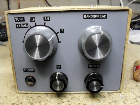
This simple receiver uses three Russian rod pentodes, a marvellous device from the cold war era and in plentiful supply to this day ( Ebay ). The set covers 1.6MHz to 8MHz, 730kHz - 1200kHz BC and 472kHz using plug in coils for the band in use. With a reasonable aerial the set is very sensitive and drives a loudspeaker at good volume, roughly 300mW. Bandspread tuning is also used to enable easy tuning of amateur stations.
The aerial is connected directly to V1 control grid, no grid tuned circuit is used. V1 is reflexed, it amplifies RF and AF simultaneously, the gain of this stage is controlled by its G2 voltage ( VR1 ). The main purpose of V1 is to prevent oscillation from the regen stage being radiated by the aerial causing interference to other stations.
At RF the anode load for V1 is tuned circuit L1 - VC1, while at AF the anode load is R3. Amplified RF from V1 is coupled to V2 control grid. V2 is configured as a regeneration stage, degree of regen is control by G2 voltage via VR2.
Demodulated audio is taken from V2 anode via C14. R11, C2 form a low pass filter thus eliminating any RF from V2 anode passing to V1. Amplified audio is taken from V1 anode via C6, R5 - C7 form another low pass filter to remove any RF/oscillation being passed to V3. A 1J29b is used as an audio output stage providing a few hundred milliwatts of output power. V3 anode load is a small 100V line transformer, the 250mW tap is used as this gives the best match and loudest volume, it presents a load impedance of roughly 40K. Standard output transformers work but with slightly reduced volume.
A range of plug in coils are used for L1, these are constructed from a piece of broom stale with copper wire pins on the bottom arranged in a B9A pattern. 1mm holes were drilled in B9A formation and suitable stout copper wire was pushed and glued into the holes, I used a two part epoxy resin. The wire used for the coil winding is 32 swg enamelled copper wire. On the broadcast band coil a "cheat " is included, a switched 470pF capacitor is used to receive CW transmissions on the new 472kHz band. The switch and capacitor are mounted on the coil ( see photos ). All coil winding details are given in the circuit diagram, the frequency ranges are approximate so the odd turn may be added / subtracted depending on stray capacitance etc.
The set works well with a short end fed, long end fed long wires will also work fine provided a step down RF transformer is used in line with the antenna, otherwise all that will be heard is loud mains hum due to the first stage acting as a audio pre amplifier with a long wire connected to its input.
The set is easy to use and its performance is very good indeed for such a simple set. Amateur stations are easily copied, both ssb and cw. Broadcast stations romp through, VR1 is useful here as it controls both RF and AF gain.
The suppressor grid ( G3 ) is internally tied to the filament/cathode in the 1J18b tube, this is not shown on the circuit.
If you are using a battery to power the tube filaments do not use a 1.5V battery, use a NiCad ( 1.2V ).
Barry Zarucki M0DGQ
HOME