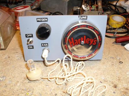
Described here is a simple regenerative receiver. No credit is taken for originality here as there are many similar circuits on the web for this type of RX, this is merely my contribution. Using a good antenna the RX will receive international shortwave broadcast stations, and ham SSB and CW transmitions although practice is reqiured in tuning ham stations. The receiver covers 2.6 MHz to 3.9 MHz approximately, all of the 80m amatuer band and some of the S/W Broadcast band.
This set is known as a TRF ( Tuned Radio Frequency ) which means that all RF stages are operating at the incoming signal frequency, unlike a superhet which converts the incoming RF signal to a fixed frequency ( Intermediate Frequency ) and it is this IF frequency where the bulk of selectivity and gain is acheived.
In this TRF set RF Regeneration gives the RX very high gain at RF and also acts as a Q - multiplier for the tuning coil which gives much improved selectivity from a single tuned circuit.
The earpeice used in this set is a crystal earpeice, these are very high impedance and should not be confused with low impedance magnetic types.
When regeneration is applied for CW / SSB reception, Tr1 becomes non linear and acts as a self oscillating mixer thus demodulating the CW / SSB signal. Extremly high gain is acheived with regeneration making the RX quite sensitive.
When used for AM reception use the regeneration control to increase the gain / selectivity but do not bring the set into osillation ( this will sound like a sqeual / hissing sound in the earpeice ). For SSB reception bring the set to "almost" oscillation, CW reception requires slightly more regeneration. The tuning of SSB and CW stations will be very sharp and requires practice, a large control knob on the tuning capacitor is recommended.
The circuit board is made using some single sided copper clad board. Copper islands are cut into the copper clad using a pad cutting tool, these are available from the G-QRP Club at resonable cost. A drill stand must be used with the pad cutting tool. Square islands can be cut with a hacksaw and glued to the main board if a pad cutting tool is not available. The given layout is a guide only, my finished board is slightly different due to a smalller piece of board used.
The tuning coil is made from some plastic overflow pipe and enamelled copper wire - see circuit diagram.
This is a fun receiver providing its limitations are realised ; it will not resolve very weak signals and its selectivity on CW / SSB signals is far from ideal but for a single transistor its performance is quite amazing.
In use best results have been had using a antenna consisting of 10 - 15 metres of wire as high as posible. Longer antennas are not of any benifit as broadcast stations tend to swamp the simple receiver. A good earth connection can be of benifit if short aerials are used - less than 10m, a shack RF earth ( external ground spike ) or a good mains earth gives good results .
Practice is required to use this simple receiver but once mastered you will appreciate the performance of this set.
Barry Zarucki M0DGQ
HOME