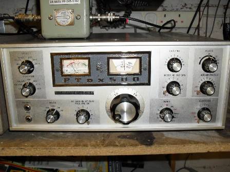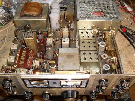

This Sommerkamp FTDX500 ( Yaesu FTDX400 rebadged ) was kindly offered to me for spares by Ian M0IDR. It seemed a shame to break it up for bits as it was complete apart from the antenna change over relay and all of the valve screening cans. Work began to restore it into working condition. The missing antenna change over relay was replaced with a chunky ( 20 amp contact rating ) two pole change over relay who's coil voltage is 4.5VDC as I had one in the junk box. The original missing relay has a coil voltage of 100VDC, these are very hard to come by now but using the modification given here any relay with a coil voltage of 4 - 12V will work fine. Firstly, the 6.3Vac heater supply is half wave rectified and smoothed to give just over 6Vdc to power the new relay coil ( if your coil requires 12VDC then use a voltage doubler circuit ). The 300 VDC ( via R34 ) supply wire connected to the original relay is now redundant so insulate well and secure. The other coil wire is still utilised as this grounds the new coil when transmitting via a contact closure from the VOX / PTT relay. The circuit for the modification is given below.
A thorough check was carried out to the transceiver to see what worked and what did not. The set would not produce much RF in tune mode TX, 40W was the best I could get. There was plenty of drive reaching the grids of the PA valves ( 6DK6's are used here, American line output tubes) and the voltages were correct in this area, so this led me to think the valves were low emission. The rarity and cost of these two valves makes the restoration prohibitive, however, I have quite a few PL519's in my junk box so a another modification was carried out. New valve bases were fitted to accommodate the PL519's and a suitable heater transformer bolted to the chassis rear ( PL519's require 40Vac for heaters so a 20 - 0 - 20 Vac transformer is used here to give 40Vac ). The addition of the transformer adds an extra 30mm to the existing depth ( the accessory plug sticks out by 30mm ). A cooling fan was fitted to the PA cage rear,voltage for this is derived from the 6.3 Vac heater supply ( doubled to 12Vdc ). The lid of the PA cage was raised by 3mm using M4 nuts as spacers to clear the top caps of the PL519's as they are slightly taller than 6KD6's.This set is rated at 440W CW DC INPUT power ( 500 PEP SSB ), measured maximum power output in tune mode ( with the transformer HT tap on 600 Vac ) is now 300W 80m to 20M, 140W on 15m and 120W on 10m.
A quick check on CW revealed the power output was only 100W, this was due to the LSB xtal being off alignment ( in CW tx mode the LSB xtal is shifted up in frequency by 800Hz so it passes through the 3.180 kHz crystal filters passband ), a quick tweak and measurement using a frequency counter soon put this right, CW output was now the same as tune mode. In LSB and USB there seemed insufficient mic gain to drive the finals to maximum power, even shouting into the mic produced little PA current. A scope on the anode of the second triode in the mic preamp confirmed low audio drive. All the voltages seemed ok around the mic preamp, the valve was removed from its base only to find a ECC82 was fitted instead of a ECC83 ( a higher gain valve ), the correct valve was fitted and correct RF output was now produced at normal voice levels.
Receive was fine apart from a distinct lack of AGC, a faulty 6BZ6 ( 1st RF amp ) was the culprit, the AGC line was 0.5V positive with the duff valve. A EF183 was used here as 6BZ6's are difficult to obtain in the UK, the EF183 works extremely well giving good AGC characteristics and has very similar characteristics to the 6BZ6 - they were both designed to be used as AGC controled vision IF amplifiers in TV sets, the only snag is having to fit a B9A base for the EF183. The set was completely aligned ( all of the IFT's were fine, the only alignment really needed was all of the 80m - 10m tank preselector coils ). The receiver is sensitive and pleasant to listen to, the VFO is very stable after 30 minutes warm up.
With the PC cooling fan fitted the PA will produce 300W of CW all day long without red anodes ( in fact I think the PSU transformer would probably fail first ) and the PA cage remains cool. PL519's are a robust valve providing they are mounted vertically, otherwise they can suffer from inter electrode shorts due to grid sag in the horizontal plane. Also, if kept cool they are extremely reliable - I ran two PL519's with 1000 volts on the anodes in a experimental linear producing 350W output with no reliability issues. As an after thought, the PA driver valve circuitry was modified to use a QQV03-10 as the driver instead of the original 6GK6. This was done out of curiosity to see if it would work ok and because 6GK6's are hard to find at reasonable price. After this modification was carried out, CW keydown power out is now 340W 80m to 20m, 200W on 15m and 170W at 10m, marvellous! The QQV03-10 is a dual VHF 10W tetrode designed for push pull VHF driver stages, here both tetrodes are wired in parallel and the valve base rewired accordingly, the screen supply is now taken from the junction of C40/CH 1 ( putting 170V on the screen grid ). This modification would also be very useful for any sets using 12BY7A's for the driver as these are now becoming expensive to buy whereas most junk boxes will contain a few QQV03-10's - I had twelve in mine, mainly from old Pye Cambridge and Pye base stations. After some thought, the transformer HT tap was switched to the 460 Vac position, the set now produces 300W CW on 20m, this was done to preserve valve life but more importantly reduce loading on the mains transformer in the hope of never having to replace it due to failure.
Barry Zarucki M0DGQ
HOME