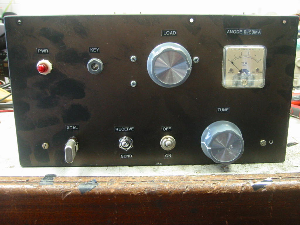
This valve CW QRP transmitter is simple to build and will not break the bank. Built to a budget, no parts where purchased, all components from the junk box and a simple aluminium box was used as a chassis
V1 is configured as a Electron Coupled Oscillator ( ECO ), G2 is utilised as a anode for feedback through the crystal to G1. This arrangement allows a low level of feedback from G2 to G1 so very little xtal heating will occur, but also the pentode acts as a high gain amplifier by taking the signal output from the anode thus producing plenty of drive. A ECO is used as there are lots of EF80's in my junk box, sadly no triodes. The keying circuit is novel and very effective,it is similar to a popular technique used in some Russian designs. No clicks or chirp is produced by this set ( see the photo of the output waveform, no sharp rising edge or overshoot and a gentle decay on the falling edge. This is a " dit " sent at a speed of 40wpm from a keyer ). Both valves are cut off when the key is up as the control grids are held at -65 Volts due to divider network R1, R2. When the key is pressed, C2 discharges ( via D1, R4 ) quickly compared to C1 so the oscillator starts before the power amplifier valve V2 gradually comes into operation as C1 discharges ( this takes a few tens of milliseconds ) thus eliminating any chirp. When the key is released, C2 now takes longer to discharge than C1 as C2 now discharges via R5 ( diode D1 is now reverse biased ) as a result the power amplifier valve gradually shuts off ( again, we are talking milliseconds here ) before the oscillator ceases, thus eliminating any clicks. So, in summation: When the key is pressed the oscillator starts first then the PA gradually starts. When the key is released the PA gradually ceases then the oscillator stops. One more important point also takes place when keying, the power amplifier valve as already mentioned has its grid held at - 65 Volts in key up, however, when key down takes place its grid is taken to - 30 Volts as R3 is now in parallel with R2 in the bias divider network thus providing the correct bias voltage necessary for V2 in key down. Power output produced is approximately 5 Watts on 80m and 3 Watts on 40m. V2 has a small amount of standing current ( approx. 15mA ) in order to reduce drive requirements from the oscillator valve. A two pole changeover switch is used for antenna routing and receiver muting during TX.
The power supply uses a mains transformer taken from a skipped broadcast set, the rest of the PSU components were from the junk box
As can be seen from the photographs this set is easy to construct. Virtually any small pentode / tetrode can be used in this set, EL84,EL82,6V6 etc. In use, simply plug in the relevant crystal and tank coil, tune anode tune capacitor for minimum anode current indicated by the meter then tune loading control for maximium RF out. Keep the anode current of V2 below 50mA. I get a great buzz from running sets like this, 5 watts and from a valve, marvellous!
Barry Zarucki M0DGQ
HOME